2.0 Basic Principles of Thermoelectric Modules & Materials
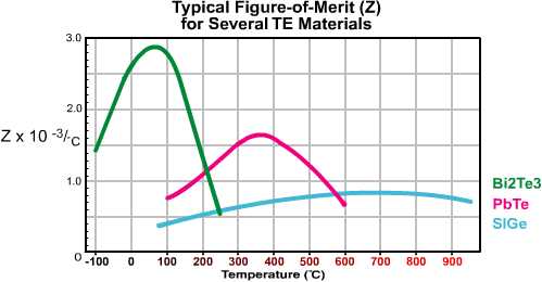
2.1 THERMOELECTRIC MATERIALS: The thermoelectric semiconductor material most often used in today’s TE coolers is an alloy of Bismuth Telluride that has been suitably doped to provide individual blocks or elements having distinct “N” and “P” characteristics. Thermoelectric materials most often are fabricated by either directional crystallization from a melt or pressed powder metallurgy. Each manufacturing method has its own particular advantage, but directionally grown materials are most common. In addition to Bismuth Telluride (Bi2Te3), there are other thermoelectric materials including Lead Telluride (PbTe), Silicon Germanium (SiGe), and Bismuth-Antimony (Bi-Sb) alloys that may be used in specific situations. Figure (2.1) illustrates the relative performance or Figure-of-Merit of various materials over a range of temperatures. It can be seen from this graph that the performance of Bismuth Telluride peaks within a temperature range that is best suited for most cooling applications.
APPROXIMATE FIGURE-OF-MERIT(Z)FOR VARIOUS TE MATERIALS

Figure (2.1) Performance of Thermoelectric Materials at Various Temperatures
2.1.1 BISMUTH TELLURIDE MATERIAL: Crystalline Bismuth Telluride material has several characteristics that merit discussion. Due to the crystal structure, Bi2Te3 is highly anisotropic in nature. This results in the material’s electrical resistivity being approximately four times greater parallel to the axis of crystal growth (C-axis) than in the perpendicular orientation. In addition, thermal conductivity is about two times greater parallel to the C-axis than in the perpendicular direction. Since the anisotropic behavior of resistivity is greater than that of thermal conductivity, the maximum performance or Figure-of-Merit occurs in the parallel orientation. Because of this anisotropy, thermoelectric elements must be assembled into a cooling module so that the crystal growth axis is parallel to the length or height of each element and, therefore, perpendicular to the ceramic substrates.
There is one other interesting characteristic of Bismuth Telluride that also is related to the material’s crystal structure. Bi2Te3 crystals are made up of hexagonal layers of similar atoms.

While layers of Bismuth and Tellurium are held together by strong covalent bonds, weak van der Waals bonds link the adjoining [Te¹] layers. As a result, crystalline Bismuth Telluride cleaves readily along these [Te¹][Te¹] layers, with the behavior being very similar to that of Mica sheets. Fortunately, the cleavage planes generally run parallel to the C-axis and the material is quite strong when assembled into a thermoelectric cooling module.
2.1.2 Bismuth Telluride material, when produced by directional crystallization from a melt, typically is fabricated in ingot or boule form and then sliced into wafers of various thicknesses. After the wafer’s surfaces have been properly prepared, the wafer is then diced into blocks that may be assembled into thermoelectric cooling modules. The blocks of Bismuth Telluride material, which usually are called elements or dice, also may be manufactured by a pressed powder metallurgy process.
2.2 THERMOELECTRIC COOLING MODULES: A practical thermoelectric cooler consists of two or more elements of semiconductor material that are connected electrically in series and thermally in parallel. These thermoelectric elements and their electrical interconnects typically are mounted between two ceramic substrates. The substrates serve to hold the overall structure together mechanically and to insulate the individual elements electrically from one another and from external mounting surfaces. After integrating the various component parts into a module, thermoelectric modules ranging in size from approximately 2.5-50 mm (0.1 to 2.0 inches) square and 2.5-5mm (0.1 to 0.2 inches) in height may be constructed.

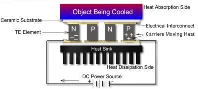
Figure (2.2) Schematic Diagram of a Typical Thermoelectric Cooler
2.2.1 Both N-type and P-type Bismuth Telluride thermoelectric materials are used in a thermoelectric cooler. This arrangement causes heat to move through the cooler in one direction only while the electrical current moves back and forth alternately between the top and bottom substrates through each N and P element. N-type material is doped so that it will have an excess of electrons (more electrons than needed to complete a perfect molecular lattice structure) and P-type material is doped so that it will have a deficiency of electrons (fewer electrons than are necessary to complete a perfect lattice structure). The extra electrons in the N material and the “holes” resulting from the deficiency of electrons in the P material are the carriers which move the heat energy through the thermoelectric material. Figure (2.2) shows a typical thermoelectric cooler with heat being moved as a result of an applied electrical current (I). Most thermoelectric cooling modules are fabricated with an equal number of N-type and P-type elements where one N and P element pair form a thermoelectric “couple.” The module illustrated in Figure (2.2) has two pairs of N and P elements and is termed a “two-couple module”.
Heat flux (heat actively pumped through the thermoelectric module) is proportional to the magnitude of the applied DC electric current. By varying the input current from zero to maximum, it is possible to adjust and control the heat flow and temperature.
Table of Contents
Do You Need More Information?
Contact your local China Advanced Ceramic thermal solutions representative.